A blog to help electrical engineers and students to learn electrical engineering topics. Basic Electrical Engineering, Power Systems, Electrical Machines, tec.. Now special course on MATLAB for Beginners.

Class

Class

Thursday, December 31, 2015

Smart Grid - The Most Trending in 2015


Introduction

Smart Grid generally refers to a class of technology being used to bring utility electricity delivery systems into the 21st century, using computer-based remote control and automation. Much in the way that a “smart” phone these days means a phone with a computer in it, smart grid means “computerizing” the electric utility grid. They offer many benefits to utilities and consumers - mostly seen in big improvements in energy efficiency on the electricity grid and in the energy users’ homes and offices.

Smart power grids are expected to accommodate increasing volumes of renewable energy sources and energy storage systems. Smart grid infrastructure also facilitates the operation of subsystems in islanded modes in cases of contingency. The field opens wide doors for fruitful work of research and development along the axes of system components, operation, restoration, protection, control, planning, design, optimization, forecasting, and scheduling.

(Photo courtesy: www.purdue.edu/discoverypark)

Like the Internet, the Smart Grid will consist of controls, computers, automation, and new technologies and equipment working together, but in this case, these technologies will work with the electrical grid to respond digitally to our quickly changing electric demand. 

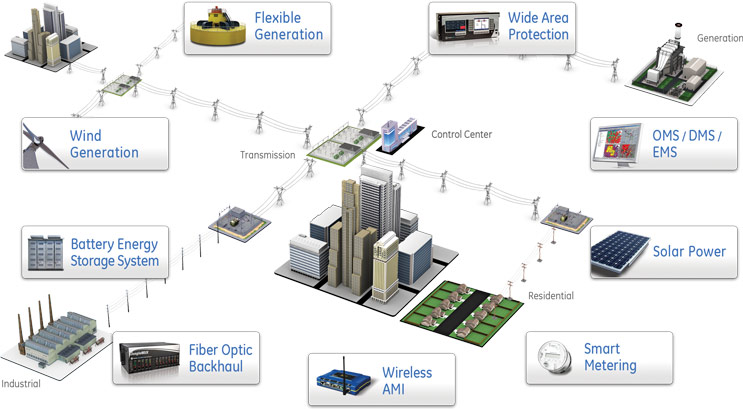
In smart grids, communications between system components represent the backbone of system operation. A huge volume of data will be available at the discretion of the operator covering a number of aspects such as load consumption, generation scheduling, and component loading. Smart grids help improve system operation in terms of reliability, controllability, and optimization. Smart Grid network uses standard communication protocols to ensure compatibility and inter-operability. 
The network connects substations, distribution grid devices, meters, and in-home devices with the utility’s head-end software to provide private communications for utility operations and secure communications to allow consumers to interact with their energy control devices.

Why Smart?

It give the consumer the information and tools required to make choices about their energy use. With a smarter grid, you can have a clear and timely picture of how much electricity you use. "Smart meters," and other mechanisms, will allow you to see how much electricity you use, when you use it, and its cost. Smart grid will add resiliency to our electric power System and make it better prepared to address emergencies. A key feature of the smart grid is automation technology that lets the utility adjust and control each individual device or millions of devices from a central location.
 
Intelligent – capable of sensing system overloads and rerouting power to prevent or minimize a potential outage; of working autonomously when conditions require resolution faster than humans can respond and cooperatively in aligning the goals of utilities, consumers and regulators.

Efficient – capable of meeting increased consumer demand without adding infrastructure.

Accommodating – accepting energy from virtually any type of source including solar and wind as easily and transparently as coal and natural gas; capable of integrating any and all better technologies and energy storage technologies. 

Motivating – enabling real-time communication between the consumer and utility so consumers can tailor their energy consumption based on individual preferences, like price and/or environmental concerns.

Quality-focused – capable of delivering the power quality necessary – free of sags, spikes, disturbances and interruptions – to power our increasingly digital economy and the data centers, computers and electronics necessary to make it run.

Resilient – increasingly resistant to attack and natural disasters as it becomes more decentralized and reinforced with Smart Grid security protocols.

“Green” – slowing the advance of global climate change and offering a genuine path toward significant environmental improvement with the improved usage of renewable energy sources.

Benefits

The benefits associated with the Smart Grid include:
  • More efficient transmission of electricity
  • Quicker restoration of electricity after power disturbances
  • Reduced operations and management costs for utilities, and ultimately lower power costs for consumers
  • Reduced peak demand, which will also help lower electricity rates
  • Increased integration of large-scale renewable energy systems
  • Better integration of customer-owner power generation systems, including renewable energy systems
  • Improved security

Micro Grid

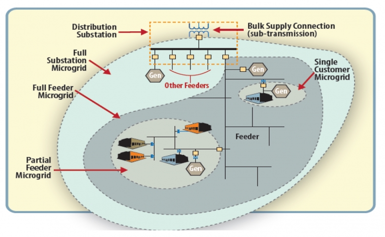
(Photo courtesy: http://energy.gov/oe/services/technology-development/smart-grid)

Microgrids are localized grids that can disconnect from the traditional grid to operate autonomously. They help mitigate grid disturbances to strengthen smart grid resilience, because they are able to continue operating while the main grid is down, and they can function as a grid resource for faster system response and recovery.
Microgrids also support a flexible and efficient electric grid, by enabling the integration of growing deployments of renewable sources of energy such as solar and wind and distributed energy resources such as combined heat and power, energy storage, and demand response. In addition, the use of local sources of energy to serve local loads helps reduce energy losses in transmission and distribution, further increasing efficiency of the electric delivery system.

References

1. www.smartgrid.gov
2. www.purdue.edu/discoverypark
3. http://energy.gov/oe/services/technology-development/smart-grid

Wednesday, December 30, 2015

Earthing - Basics


Earthing is a connection which connects parts of the electric circuit with the ground or earth. Regulations for earthing system vary considerably among countries and among different parts of electric systems. Most low voltage systems connect one supply conductor to the earth (ground). Normally, the earth connection should be without the intervention of a fuse, switch, circuit breaker, resistor etc.

Need for earthing:

  • Stable operation of the system. 
  • Safety of the men and material. 
  • Protection against lightning. 

 Some of the important terms related to grounding:
  • Ground
A ground is a conducting connection, whether intentional or accidental, between an electrical circuit or equipment and earth or to some conducting body that serves in place of earth.
  • Grounded
Grounded means connected to earth or to some conducting body that serves in place of earth.
  • Grounded conductor
A system or circuit conductor that is intentionally grounded, such as grounded neutral conductor.
  • Grounding conductor
A conductor used to connect equipment or the grounded circuit of a wiring system to a grounding electrode or electrodes.
  • Grounded rod
A conductive metal rod driven in the ground to serve as a grounding electrode, usually 10 to 15 ft long and 1 in. In diameter.

  • Ground loop
A continuous ground electrode of wire encircling the area and connecting three or more ground rods.
  • Ground clip
A metal clip connected to the ground loop to enable one or more extensions of the ground loop to be extended.
  • Ground well
A concrete encasement around the ground rod to allow access to the rod to measure ground resistance.
  • Ground grid
A steel mesh or wire grid buried beneath the surface of an area to serve as a ground electrode.
  • Ground bus
A metal plate to which multiple ground leads are attached.

Methods of earthing:

There are two methods of earthing, namely
  1. Pipe earthing 
  2. Plate earthing 

1. Pipe earthing


Pipe earthing is done by permanently placing a pipe in wet ground. The pipe can be made of steel, galvanized iron or cast iron. Usually GI pipes having a length of 2.5m and an internal diameter of 38mm are used. The pipe should not be painted or coated with any-non-conducting material.


The pipe should be placed at least l.25m below the ground level and it should be surrounded by alternate layers of charcoal and salt for a distance of around 15 cm. This is to maintain the moisture level and to obtain lower earth resistance. The earth lead of sufficient gauge should be firmly connected to the electrode and it should be carried in a GI pipe at a depth of 60cm below the ground level.

2. Plate earthing


The plate electrode should have a minimum dimension of 600x600x3.15mm for copper plate or 600x600x6.3mm for GI plates. The plate electrode should be placed at least 1.5m below the ground level. The earth conductor is to be securely connected to the plate by means of bolts and nuts. The bolts and nuts should be of the same material as that of the plate. The earth conductor should be carried in a GI pipe buried 60 cm below the ground level. The prate electrode should be surrounded by a layer of charcoal to .reduce the earth resistance.


For more details about power system earthing refer to Earthing in electrical network – purpose, methods and measurement

Saturday, December 26, 2015

Comparison between Magnetic and Electrical Circuits


When we compare the Magnetic and Electrical circuits, M.M.F is analogous to E.M.F., flux to current and reluctance to resistance.

In electric circuit as per Ohm’s Law:
                             I = V / R

Similarly in magnetic circuit when Ohm’s Law is applied:

                           Magnetic flux = m.m.f / Reluctance

The laws of reluctance in series and parallel are the same as those for resistance in series and parallel.

Comparison


Thursday, December 24, 2015

Types of DC Generator and Their Characteristics


Types of DC Motor

D.C. generators are classified according to the method of their field excitation. These groupings are:
  1. Permanent magnet dc generators, where a permanent magnet is used to establish flux in the magnetic circuit.
  2. Separately-excited generators, where the field winding is connected to a source of supply other than the armature of its own machine.
  3. Self-excited generators, where the field winding receives its supply from the armature of its own machine, and which are sub-divided into
    1. Shunt
    2. Series, and
    3. Compound wound generators.
When the field winding of a d.c. machine is connected in parallel with the armature, as shown in Fig, the machine is said to be shunt wound. If the field winding is connected in series with the armature, then the machine is said to be series wound. A compound wound machine has a combination of series and shunt winding.

Characteristics

(a) Separately-excited generator


The two principal generator characteristics are the generated voltage/field current characteristics, called the open-circuit characteristic and the terminal voltage/load current characteristic, called the load characteristic. Typical separately-excited generator characteristics are shown in Figure.

When a load is connected across the armature terminals, a load current Ia will flow. The terminal voltage V will fall from its open-circuit e.m.f. E due to a volt drop caused by current flowing through the armature resistance, shown as Ra.
Terminal voltage,
E − IaRa

(b) Shunt wound generator

In a shunt wound generator the field winding is connected in parallel with the armature as shown in Figure. The field winding has a relatively high resistance and therefore the current carried is only a fraction of the armature current.
Terminal voltage, V = E - IaRa
Ia = If + I from Kirchhoff’s current law, where,
Ia = armature current,
If = field current = V/Rf
and I = load current

As the load current on a generator having constant field current and running at constant speed increases, the value of armature current increases, hence the armature volt drop, IaRa increases. The generated voltage E is larger than the terminal voltage V and the voltage equation for the armature circuit is V = E - IaRa. Since E is constant, V decreases with increasing load.


(c) Series-wound generator

In the series-wound generator the field winding is connected in series with the armature

Thus E is proportional to flux. For values of current below magnetic saturation, the flux is proportional to the current, hence E α I. For values of current above those required for magnetic saturation, the generated e.m.f. is approximately constant. The values of field resistance and armature resistance in a series wound machine are small; hence the terminal voltage V is very nearly equal to E.

In a series-wound generator, the field winding is in series with the armature and it is not possible to have a value of field current when the terminals are open circuited, thus it is not possible to obtain an open-circuit characteristic.

(d) Compound-wound generator

In the compound-wound generator two methods of connection are used, both having a mixture of shunt and series winding, designed to combine the advantages of each. Fig.(a) shows what is termed a long-shunt compound generator, and Fig.(b) shows a short-shunt compound generator. The latter is the most generally used form of D.C. generator.
 
In cumulative-compound machines the magnetic flux produced by the series and shunt fields are additive. Included in this group are over-compounded, level-compounded and under-compounded machines – the degree of compounding obtained depending on the number of turns of wire on the series winding.


Review Questions

1. With the increases in field excitation of a DC generator, its generated emf ________________
  1. decreases.
  2. increases.
  3. remains constant.
  4. increases up to a limit and then remains almost constant. 

2. Which of following DC generator will be in a position to build up without any residual magnetism in the field?
  1.  Compound. 
  2. Shunt.
  3. Series.
  4. None of them

3. Which of the following DC generators has rising V-I characteristics?
  1. Compound. 
  2. Shunt.
  3. Series.
  4. None of them.

4. The ___________________ generator has the poorest voltage regulation.
  1. under-compounded.
  2. differential compounded. 
  3. shunt. 
  4. over compounded.

5. The voltmeter connected across a generator reads voltage same at no load and at full load (rated). The generator is of the type
  1. level compound.
  2. series generator.
  3. short - shunt generator.
  4. shunt generator.


Tuesday, December 22, 2015

Types of Electrical Drawings


Electrical drawings generally fall into four broad categories:
  1. Plans
  2. Schedules
  3. Diagrams
  4. Details and/or Elevations
We will examine each or these categories briefly and determine their place in the overall picture or project .

Electrical Plans and Plan Views

The electrical floor plan tells the electrician where each electrical device and piece of equipment is to be located related to the architectural features of the area. It shows the electrician where and how the conductors are to run. It helps locate the incoming service. Electrical plans are also used for estimating installation and material costs. By examining a plan, the electrician can take off, that is, count, the number of switches, outlets, fixtures, feet of wire, etc., that may be required for a particular job.

Types of Plans

1. Power plan

2. Lighting plan

3. Instrument plan

4. Underground plan

5. Equipment plan

6. Grounding plan

7. Conduit plan

Schedules

Schedules are generally full sized drawings presenting a summary or collection of information. They are usually in tabular form. There should be some semblance of organization in a schedule, be it numerical, alphabetical or otherwise, so that the information is retrievable without scrutinizing every item in the schedule. The information should be complete with reference drawings, legends, or notes to make it self-explanatory.

Types of Schedules

1. Conduit and Cable Schedule

2. Junction box schedule

3. Transformer schedule

4. Fixture or device schedule

5. Lighting Panel (MCC) schedule

Electrical Diagrams

Diagrams show the electrical path, device wiring, sequence of operation, device relationship, or connections and hookups of the electrical installation. Occasionally the drawing types are combined or used as details for one or another type of drawing.

Types of Diagrams

1. One- line diagram

2. Schematic wiring diagram

3. Ladder diagram

4. Field wiring diagram

5. Panel wiring diagram

6. Instrument wiring diagram

7. Interconnection diagram

8. External connection diagram

9. Logic diagram

Detail Drawings

Detail drawings, or sheets, arc full-sized drawings showing complete information on a specific installation, conduit routing, equipment placement or connection, and so on. They may be elevation or plan views and are generally to a larger scale so that more detail can be called out. Several details, some times as many as nine, appear on one sheet.

Detail sheets are usually limited to one category of details per sheet, such as power details, lighting details, or grounding details

Review Questions

  1. List the four general categories of Electrical Drawings 
  2. List any four types of electrical plan 
  3. Write name of any four types of electrical diagrams 
  4. What are the different types of electrical schedules?

Monday, December 21, 2015

Resistance - Series and Parallel Connection


Series and parallel Connections

When several devices are connected end to end in such a way that there is only one path for the current to flow and so, the same current flows through each, then such a circuit is called a "series circuit". When several devices are connected to a common voltage in a certain manner that they provide alternative paths for the current.  Where the current in each path (device) will depend on its resistance.  Such a circuit is called “parallel circuit”.

Resistances in Series

When three resistors, R1, R2 and R3 are connected end to end as shown in the figure below, then it would be referred as resistances in series. In case of series connection, the equivalent resistance of the combination, is sum of these three electrical resistances.

Total voltage applied across the combination of resistances in series, is V. Let the current in the circuit is I. So this current I will pass through the resistance R1, R2 and R3. Applying Ohm’s law , it can be found that voltage drops across the resistances will be V1 = IR1, V2 = IR2 and V3 = IR3.
From figure, the total voltage is the sum of voltage drop across R1, R2 and R3, is V1, V2 and V3 respectively, 

            then     V   = V1 + V2 + V3
            \         V = IR1 + IR2 + IR3

            or         V = I (R1 + R2 + R3)

Now, if we consider the total combination of resistances as a single resistor of electric resistance value R, then according to Ohm’s law ,

                        V = IR

              \     IR = II (R1 + R2 + R3)

finally,            R = R1 + R2 + R3

So the above proof shows that equivalent resistance of a combination of resistances in series is equal to the sum of individual resistance. If there were n number of resistances instead of three resistances, the equivalent resistance will be
                       R = R1 + R2 + R3 + ………………..+Rn


Resistances in Parallel

Let’s three resistors of resistance value R1, R2 and R3 are connected in such a manner, that right side terminal of each resistor are connected together as shown in the figure below, and also left side terminal of each resistor are also connected together. This combination is called resistances in parallel.

If a voltage, V is applied across this combination, then it will draw a current I. As this current will get three parallel paths through these three electrical resistances, the electric current will be divided into three parts. Say currents I1, I1 and I1 pass through resistor R1, R2 and R3 respectively. The total source current will be sum f branch currents,

                   I = I1 + I2 + I3

Now, as from the figure it is clear that, each of the resistances in parallel, is connected across the same voltage source, the voltage drops across each resistor is same as source voltage V.

Hence,        I1 = V/R1I2 = V/R2 and I3 = V/R3,

and             I = V ⁄ R
where R is the equivalent resistance of the combination.
    \         V ⁄ R = V/RV/RV/R3
           
                   1 ⁄ R = 1/R1/R1/R3

The above expression represents equivalent resistance of resistor in parallel. If there were n number of resistances connected in parallel, instead of three resistances, the expression of equivalent resistance would be
                  1/R = 1/R1 + 1/R2 + 1/R3 + .......... + 1/Rn


Problem Solving

Example 1 : Three resistors of 5.8W, 10.7 W  and 6.5W are connected in series across a 127 V supply.  What is

a.     the total resistance of the circuit
b.     the total current in the circuit, and
c.   the voltage across each resistor?

Example 2 :  Find the effective resistance of 20 W,  30W  and 6W resistances connected in parallel.


Example 3 : In the circuit as shown in Figure R1 = 40 W, R2=120W, R3 = 80W. If the supply voltage V is equal to 220V then find out;


a.     The total resistance
b.     The total current
c.     The current in each resistance and
d.   Voltage across each resistance.


Saturday, December 19, 2015

Energy and Power in an Electric Circuit


Energy is the ability to do work.
Power is the rate at which energy is used.
Power, symbolized by P, is a certain amount of energy used in a certain length of time, expressed as follows:
 Power =    
                 
Energy is measured in joules (J), time is measured in seconds (s), and power is measured in watts (W). 
 Energy in joules divided by time in seconds gives power in watts. 
 One watt is the amount of power when one joule of energy is used in one second.

Power in Electric Circuits

 In addition to voltage and current, another important parameter in an electric circuit is power. Power is the time rate of expending or absorbing energy.
                    
                  P = V I                                                                                
Power is the combination of both voltage and current in a circuit. Remember that voltage is the specific work (or potential energy) per unit charge, while current is the rate at which electric charges move through a conductor. We can get an equivalent expression for power by substituting for voltage and current from ohm's law.

                   P =   

                   P = I2R      

In an open circuit, where voltage is present between the terminals of the source and there is zero current, there is zero power dissipated, no matter how great that voltage may be. Since P=VI and I=0 and anything multiplied by zero is zero, the power dissipated in any open circuit must be zero. Likewise, if we were to have a short circuit constructed of a loop of superconducting wire (absolutely zero resistance), we could have a condition of current in the loop with zero voltage, and likewise no power would be dissipated.    
Power flow in an electrical device may be positive or negative. Some devices called passive components or loads; 'consume' electric power from the circuit, converting it to other forms of energy. Some devices called active devices or power source convert  from some other type of energy, such as mechanical energy or chemical energy to electric energy. Some devices can be either a source or a load, depending on the voltage and current through them, for example, a rechargeable battery. 
Electric power flowing out of a circuit into a component is arbitrarily defined to have a positive sign, while power flowing into a circuit from a component is defined to have a negative sign. Thus passive components have positive power consumption, while power sources have negative power consumption.

The Kilowatt-hour (kWh) Unit of Energy

 Since power is the rate at which energy is used, power utilized over a period of time represents energy consumption.  If you multiply power and time, you have energy.
W = Pt
When you pay your electric bill, you are charged on the basis of the amount of energy you use, not the power.  Because power companies deal in huge amounts of energy, the most practical unit is the kilowatt-hour. You use a kilowatt-hour of energy when you use one thousand watts of power for one hour.  For example, a 100 W light bulb burning for 10 h uses 1 kWh of energy.
 W = Pt = (100 W) (10 h) = 1kWh
                                                      

Problem Solving                                                                                           


Example 1

Calculate the power in each of the three circuits of Figure 1.


Figure 1.
Solution
In circuit (a), V and I are known.  Therefore, use Equation (1-8).
 P = VI = (10 V)(2 A) = 20 W
In circuit (b), I and R are known.  Therefore, use Equation (1-9).
 P = I2= (2 A) 2(47W) = 188 W
In circuit (c), V and R are known.  Therefore, use Equation (1-10).
 P = = 2.5 W


Friday, December 18, 2015

DC Generator Operating Principle - e.m.f. Equation


The basic principle of a DC machine is Faraday's laws of electromagnetic induction. According to these law, when an conductor moves in a magnetic field it cuts magnetic lines force, due to which an emf is induced in the conductor. The magnitude of this induced emf depends upon the rate of change of flux (magnetic line force) linkage with the conductor.When the armature rotates, the armature conductors cut the flux produced by the field windings (poles). Hence an emf is induced in the armature winding. The direction of induced current is given by Fleming’s right hand rule.
  
Let          Φ – Flux per pole in Wb
               Z – total number of conductors on the armature
               P – number of poles
               A – number of parallel paths on the armature
                           ( = P for Lap and = 2 for Wave)
               N – Speed of rotation of armature in rpm
               E – average emf induced
Then, total flux cut by a conductor taking one complete revolution,
d Φ = P Φ
Time taken for one complete revolution,
                        dt = 60/N seconds
According to faradays law of electromagnetic induction,
Emf induced per conductor,
                 

If there is Z number of conductors connected in A number of parallel paths,
                volts
Since, A, P, Z are constants,
                        E α N Φ